Converter Selector
Converting 3G/HD-SDI and HDMI signals. Ideal if you have limited space, the commercial-grade is not enough and power consumption is critical.
Filter
–
Full-HD AHD/TVI-HDMI Converter
Experience high-resolution video transmission with our Full-HD AHD/TVI to HDMI converter. Ideal for systems with HD input/output resolution, efficient power consumption and compact design
Product number: BA2010
Price on request
NA1011-ET| 3G/HD-SDI TO HDMI NANOCONVERTER
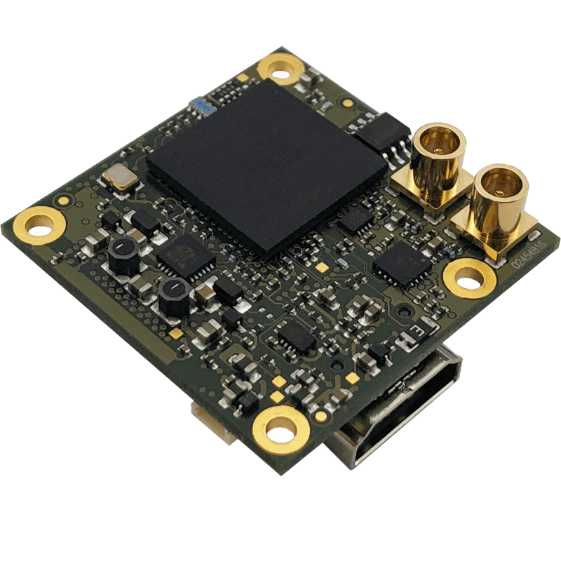
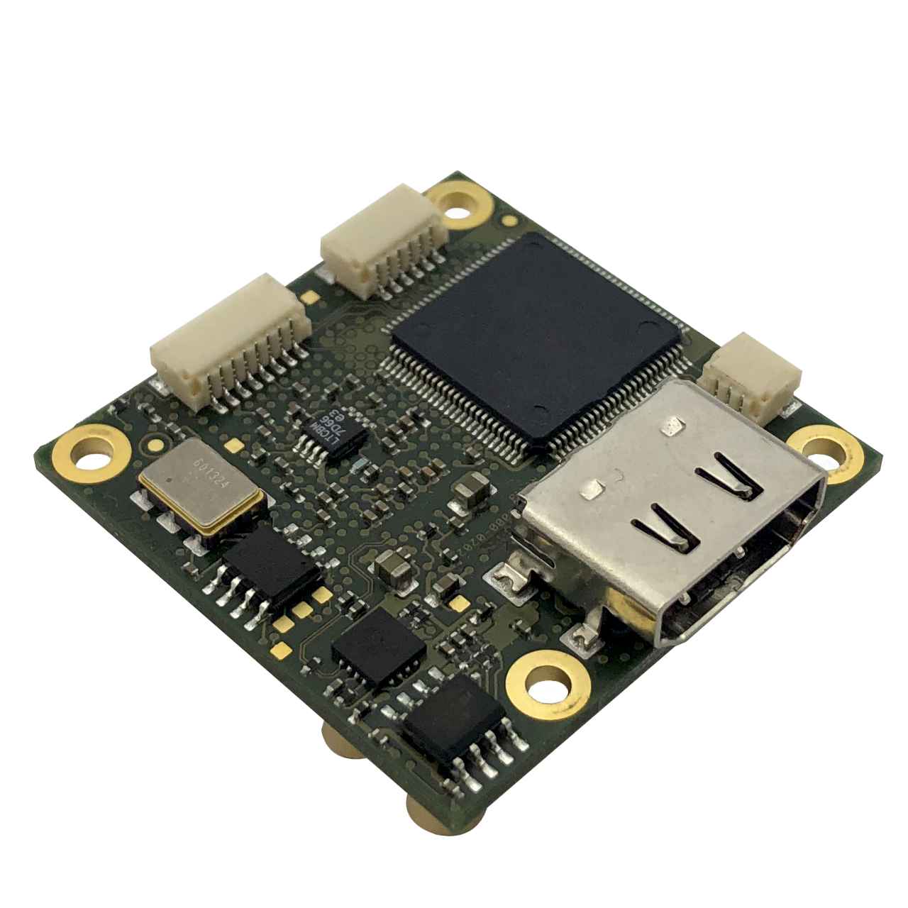
The NanoConverter NA1011 from AIVION is part of a family of small form factor solutions for transmitting and receiving standard based video signals over different physical media such as coaxial cables and optical fibre. Different video formats and interface standards are supported from the transmitter and receiver side including DVI, HDMI, CVBS, YPbPr, RGB, 3G-SDI, HD-SDI and SD-SDI. Features One 3G-SDI/HD-SDI Input 75 Ohm MCX jacks connector. Supporting bit rates due to SMPTE292M and SMPTE424M (level A) 1.485 Gbps 1.485/1.001 Gbps 2.97 Gbps 2.97/1.001 Gbps One SDI loop out with reclocking 75Ohm MCX jacks connector. One HDMI output 19 pin HDMI connector. Compliant to HDMI 1.3 No HDCP support Output Data format RGB444, 3x10 bit Extendet Temperature Range -25°C to +70°C (-13°F to 158°F), Humidity 20% to 70% Small form factor PCB dimensions 38mm x 38mm Native video signal processing No image scaling, no format conversion. Download NA1011-ET Datasheet NA1011-ET Block Diagram Operating Range -25°C to +70°C (-13°F to 158°F), Humidity 20% to 70% Vin (DC) min typ max 5V 12V 18V Input Current Requirements At 25°C ambient temperature Vin 3G Operation HD Operation Condition 5V 510mA 450mA Shutdown = Vin or OPEN 12V 220mA 200mA Shutdown = Vin or OPEN 18V 160mA 145mA Shutdown = Vin or OPEN 5-18V < 10mA < 10mA Shutdown = GND NA1011-ET PCB Connectors J3 HDMI Output Connector Samtec HDMR-19-02-F-SM-PF Pin assignment due to HDMI standard J2 (In)/ J7 (Out) 3G-SDI and HD-SDI Connectors MCX 75Ohm The NA1011-ET has straight MCX connectors. Right angled MCX connectors are optional available. J1 Power Connector JST SM03B-SRSS-TB Pin Signal 1 Vin DC input, 5V to 18V 2 Shutdown/Reset, has pull up resistor of 4,7kOhm to Vin 3 GND (0V) J4 Serial Control Interface JST SM08B-SRSS-TB Pin Signal 1 reserved, do not connect 2 reserved, do not connect 3 reserved, do not connect 4 GND 5 RX data (host to device), 3.3V TTL, 4V max. 6 TX data (host to device), 3.3V TTL, 4V max. 7 GND 8 reserved, do not connect NA1011-ET PCB Outline Notes NA1011-ET The Nanoconverter products are RoHS, REACH and UL/UR compliant. The device detects and measures video input parameter and adjusts all necessary settings accordingly. Manual control is not required. However, the serial control interface can be used for status checking. Any terminal software can be used, whereas parameters have to be set to 38400bps, 8 data bits, no parity and 1 stop bit (8N1). No handshake must be used The current device version does not support audio. The device version does not process HDCP encrypted HDMI input signals. NA1011-ET | Production Kit Partnumber Content NA1011-ET Converter with straight MCX connectors TLCK-FL03-150 3pin flying leads cable for power, lead length = 15cm / 5.9inch
Product number: NA1011-ET
Price on request
NA1012-ET | HDMI to 3G/HD-SDI Converter
The NanoConverter NA1012-ET from AIVION is part of a family of small form factor solutions for transmitting and receiving standard based video signals over different physical media such as coaxial cables and optical fibre. Different video formats and interface standards are supported from the transmitter and receiver side including DVI, HDMI, CVBS, YPbPr, RGB, 3G-SDI, HD-SDI and SD-SDI. Features One HDMI input 19 pin HDMI Connector. Compliant to HDMI 1.4a and DVI 1.0.Input format support: RGB 444 YCbCr 444 YCbCr 422 Two SDI outputs 75 ohm MCX jacks connector. Supporting bit rates due to SMPTE292M and SMPTE424M 1.485 Gbps 1.485/1.001 Gbps 2.97 Gbps 2.97/1.001 Gbps Full-HD Support Supported Video formats: 1080p at 50/25/24/59.94/29.97/23.98/60/30 1080i at 50/59.94/60 720p at 50/ 59.94/60 Extendet Temperature Range -25°C to +70°C (-13°F to 158°F), Humidity 20% to 70% Small form factor PCB dimensions 38mm x 38mm Native video signal processing No image scaling, no format conversion. Download NA1012-ET Datasheet NA1012-ET Block Diagram J2 HDMI Input Connector Samtec HDMR-19-02-F-SM-PF Pin assignment due to HDMI standard J5 / J6 3G-SDI and HD-SDI Output Connectors MCX 75Ohm J1 Power Connector JST SM03B-SRSS-TB Pin Signal 1 Vin DC input, 5V to 18V 2 Shutdown/Reset, has pull up resistor of 4,7kOhm to Vin 3 GND (0V) J3 Serial Control Interface JST SM08B-SRSS-TB Pin Signal 1 reserved, do not connect 2 reserved, do not connect 3 reserved, do not connect 4 GND 5 RX data (host to device), 3.3V TTL, 4V max. 6 TX data (host to device), 3.3V TTL, 4V max. 7 GND 8 reserved, do not connect NA1012-ET PCB Outline Notes NA1012-ET The Nanoconverter products are RoHS, REACH and UL/UR compliant. The NA1012 converts video signals received from a DVI or HDMI source for transmission over an 3G/HD- SDI interface which requires clock signals to be in a well defined range. This might not be the case when standard HDMI or DVI output of desktop computers, laptop computers ot other consumer devices are used as signal source. The HDMI/DVI TMDS input clock requirements are: 3G mode: 148.5MHz or 148.5 MHz/1.001 +/- 60ppm HD mode: 74.25MHz or 74.25MHz/1.001 +/- 80 ppm The device detects and measures video input parameter and adjusts all necessary settings accordingly. Manual control is not required. However, the serial control interface can be used for status checking. Any terminal software can be used, whereas parameters have to be set to 38400bps, 8 data bits, no parity and 1 stop bit (8N1). No handshake must be used. The current device version does not support audio. The device version does not process HDCP encrypted HDMI input signals. NA1012-ET | Production Kit Partnumber Content NA1012-ET Converter with straight MCX connectors TLCK-FL03-150 3pin flying leads cable for power, lead length = 15cm / 5.9inch
Product number: NA1012-ET
Price on request
NA1012B-ET | HDMI TO 3G/HD-SDI CONVERTER (board to board connector)
Converter Kit: Only Board - No Evaluation Adapter
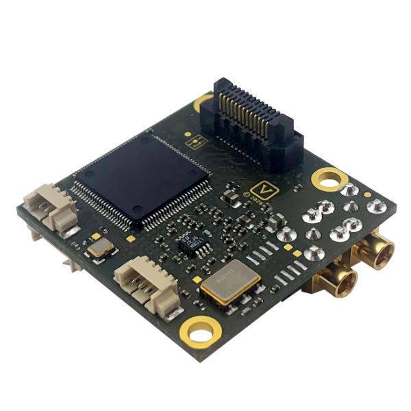
The NanoConverter NA1012B-ET from AIVION is a very small form factor HDMI to SDI converter module. It is designed for applications where minimum size and a wide operating temperature range have the highest priority. For this purpose, HDMI input video and power supply voltage are supplied over a board2board connector eliminating the need for HDMI and power cables. The converter module can be easily plugged onto system boards, having a mating board2board connector available. SDI video output is available on two right-angled MCX coaxial connectors. Features One HDMI input HDMI input over board to board connector. Compliant to HDMI 1.4a and DVI 1.0.Input format support: RGB 444 YCbCr 444 YCbCr 422 Two SDI outputs 75 ohm MCX jacks connector. Supporting bit rates due to SMPTE292M and SMPTE424M 1.485 Gbps 1.485/1.001 Gbps 2.97 Gbps 2.97/1.001 Gbps Full-HD Support Supported Video formats: 1080p at 50/25/24/59.94/29.97/23.98/60/30 1080i at 50/59.94/60 720p at 50/ 59.94/60 Extendet Temperature Range -40°C/+85°C = -40°F/185°F Humidity: 20% - 80% Small form factor PCB dimensions 38mm x 38mm Native video signal processing No image scaling, no format conversion. Download NA1012B-ET Datasheet V1.0.2 NA1012B-ET Block Diagram NA1012B-ET PCB Connectors J2 Board to Board Connector Samtec Board2Board, ERM8-013-05.0-L-DV-TR Samtec ERF8-013-05.0-L-DV-TR mating connector is required on the system board Pin Signal 1 Reset (same operation as J1 pin2) 4,6 HDMI_CLK_N, HDMI_CLK_P 17,19 HDMI_DATA2_N, HDMI_DATA2_P 11,13 HDMI_DATA1_N, HDMI_DATA1_P 5,7 HDMI_DATA0_N, HDMI_DATA0_P 2,3,9,14 GND(0V) 15,21 GND(0V) 18 HDMI_HPD (hot plug detect) 8 HDMI_CEC 10,12 HDMI_DDC_CLK, HDMI_DDC_DATA 16 HDMI_5V_input 20 VIN DC supply input (same as J1 pin1) 23,25 RXD_TTL, TXD_TTL (same as J3 pin1/pin2) 22,24,26 Do not connect J5 / J6 3G-SDI and HD-SDI Output Connectors MCX 75 ohms, Samtec MCX7-J-P-H-RA-TH1 J1 Power Connector Wuerth WTB 1.25mm, 653 103 131822 Pin Signal 1 VIN, DC Supply voltage input 2 Reset (has 4k7 pullup to VIN) - Pull pin 2 to GND(0V) for 1ms or longer for reset, leave open for normal operation. 3 GND (0V) J3 Serial Control Interface Wuerth WTB 1.25mm, 653 104 131822 Pin Signal 1 RXD_TTL (3,3V debug interface data input) 2 TXD_TTL (3,3V debug interface data output) 3 GND (0V) 4 Do not connect J2 Board to Board Connector Signal/Pin Assignement NA1012B-ET PCB Outline Notes NA1012B-ET NA1012B-ET converts video signals received from a DVI or HDMI source for transmission over an 3G/HD-SDI interface which requires clock signals to be in a well defined range. This might not be the case when standard HDMI or DVI output of desktop computers, laptop computers ot other consumer devices are used as signal source. The HDMI/DVI TMDS input clock requirements are: 3G mode: 148.5MHz or 148.5 MHz/1.001 +/- 60ppm HG mode: 74.25MHz or 74.25MHz/1.001 +/- 80 ppm The current device version does not support audio. NA1012B-ET does not process HDCP encrypted HDMI input signals. The device detects and measures video input parameter and adjusts all necessary settings accordingly. Manual control is not required. However, the serial control interface can be used for status checking. Terminal software like TeraTerm can be used, whereas parameters have to be set to 38400bps, 8 data bits, no parity and 1 stop bit (8N1). No handshake must be used. Depending on the system configuration and thermal as well as mechanical design of the system board, a heat sink might be required. In such a case the heat sink or heat pipe should contact to one of the devices marked with a yellow square (see images below), NA1012B-ET Heat Sink EK-PA1131 For test and evaluation purposes adaptor EK-PA-1131 is available. It provides a HDMI A-type connector for video input as well as USB2 connector which can be used to supply 5V DC power to NA1012B-ET. In addition it allows easy access to the debug/status port by an USB2 UART. Power and Environment Power Input 5V to 15V DC regulated supply input voltage range Characteristics PD = 2.1W (12V DC, video 1080p60) IDD = 0.17A (TA = 25°C, Humididty = 40%) Operting Conditions Ambient temperature (min/max) -40°C/+85°C = -40°F/185°F Humidity: 20% - 80% Storage Conditions Ambient temperature (min/max) -10°C/+60°C = 14°F/140°F Humidity: 20% - 80% NA1012B-ET | Production Kit Partnumber Content NA1012B-ET HDMI to 3G/HD-SDI Converter Board NA1012B-ET-EXT | Evaluation Extension Partnumber Content EK-PA-1131 Evaluation Adaptor for NA1012B-ET TL-EVK-USB2-A-MICROB USB 2.0 Cable with a USB 2.0-A male and a USB 2.0 micro-B male connector PS-EP-TA20EWE USB Power supply (5 V/2A or 9V/1,67A) CK-MCX-BNC MCX to BNC connector cable TL-EVK-HDMI High Speed HDMI Cable. HDMI-A male > HDMI-A male 4K 2 meter
Product number: NA1012B-ET-1
Price on request
NA4K2022 6 Gbps / DL 3Gbps UHD HDMI-SDI Converter
The NanoConverter NA4K2022 from AIVION is a small form factor HDMI 1.4b to serial digital video (SDI) converterer. Video input signals are equalized, decoded, processed and output over coaxial connectors. 6G-SDI output is compliant to SMPTE ST2081-10 MODE 1 mapping, Dual Link 3G-SDI output is compliant to SMPTE ST425-3, 2si mapping and 3G-SDI FHD output is compliant to SMPTE ST425-1 level A standards. NA4K2022 provides a status information interface based on RS232 or 3.3V TTL level. A ten wire flying leads cable for power input and status output is included. Features HDMI 1.4b input Full size HDMI-A connector 4:2:2 YCbCr sampling, 2x8bit per Pixel DVI input 4:4:4 RGB sampling, 3x8bit per Pixel Supported pixel clock frequencies (HDMI/DVI input): - UHD: 297MHz, 297MHz/1.001 - FHD: 148.5MHz, 148.5MHz/1.001 Two SDI outputs (Samtec MCX7-J-P-H-ST-TH1) 75 MCX 75 Ohm straight coaxial connectors (Standard) UHD 6G-SDI: SMPTE ST2081-10 MODE 1 UHD Dual Link 3G-SDI: SMPTE ST425-3, 2si mapping FHD 3G-SDI: SMPTE ST425-1 level A UHD Support Supported Video formats: UHD: 3840x2160p30, 3840x2160p29.97, 3840x2160p25 FHD: 1920x1080p60, 1920x1080p59.94, 1920x1080p50 Temperature Range -5°C to +60°C (= 23°F/140°F), Humidity 20% to 80% Small form factor PCB dimensions 46mm x 60mm Native video signal processing No image scaling, no format conversion. Download NA4K2022 Datasheet NA4K2022 Block Diagram NA4K2022 PCB Connectors J2 HDMI Input Connector Full size HDMI-A connector J7 / J8 SDI Output Connectors Samtec MCX7-J-P-H-ST-TH1 Mode J7 J8 UHD 6Gbps No Output 6G-SDI UHD 3Gbps Link1 of Dual Link 3G-SDI Link2 of Dual Link 3G-SDI FHD 3G-SDI 3G-SDI (same signal as J7) J6 Board feature extension connector Please contact us for further information J1 Serial Control Interface JST SM10B-SRSS-TB Pin Signal 1 DC Supply voltage input 2 DC Supply voltage input 3 GND (0V) 4 GND (0V) 5 Reset - Pull pin 5 to GND(0V) for 1ms or longer for reset, leave open for normal operation. 6 GND 7 TXD_TTL (serial IF transmit 3.3V) 8 RXD_TTL (serial IF receive 3.3V) 9 RXD_232 (serial IF receive RS232 level) 10 TXD_232 (serial IF transmit RS232 level) NA4K2022 PCB Outline NA4K2022 | Production Kit Partnumber Content NA4K2022 Converter with straight MCX connectors TLCK-FL10-150 10 pin flying leads cable for power and control(RS232/TTL), length 15cm
Product number: NA4K2022
Price on request


