Camera & Video Interfaces for Medical and Health
There are several requirements for video systems in the medical market. In general this market is asking for video systems that do not add artifacts to the video image. For that reason our interfaces and transmission systems are using uncompressed video. Our solutions are usually used in three different fields of applications:
Surgery Lamps
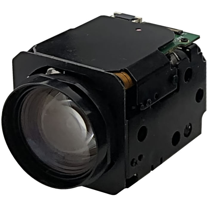
In more and more hospitals it becomes a standard to have surgery lamps that offer embedded video systems to allow documentation and monitoring. Usually, block cameras are preferred since they do allow zoom and autofocus in combination with a small form factor. Depending on the position of the Monitor we offer HDMI or SDI based transmission technology. Using our interfaces and converters it’s possible to mix those standards and use the SDI technology to bridge a long distance from the Camera to the Monitor and convert this SDI signal into HDMI to enable the usage of standard HDMI Monitors.


Dermatology
If the human skin should be observed a computing unit usually is postprocessing the video stream. Nevertheless, that video must not have any compression artefacts since those artefacts could generate wrong results. We are using uncompressed video together with a USB3 interface (UVC). Connecting a small block camera to our USB3 interfaces allows to display or postprocess the video with a computer.
Systems for visually handicapped persons
To support visually handicapped persons zoom camera blocks with good zoom lenses and fast autofocus capabilities are a good choice. Also here it is important that the camera system is providing video with low latency since it simplifies the usage to position the text under the lens. Video systems that are directly connected to a Monitor are using very often HDMI connectors.

Related 4K Products
TL4K1152 | 4K HDMI
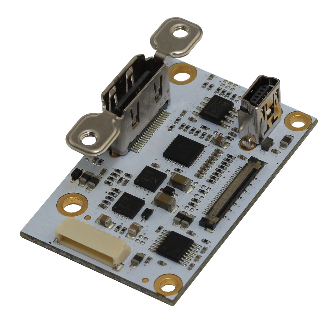
The TL4K1152 is a small form factor digital serial video transmitter from AIVION. Small form factor with an attractive price are some of the main features of the TL4K1152. It supports the new trend setting Sony block camera FCB 4K Series from Sony via an HDMI output. Camera control can be managed through an RS232 port. Via the available USB2 interface firmware updates can be obtained. Features: One HDMI 1.4b video output Up to 2160p30 UHD, FHD, HD video format support Integrated input signal equalizer Ultra high speed 3.4Gbps cable driver Small Form Factor Small form factor 46mm x 30mm Camera Control RS232 level serial camera control interface 3.3V TTL level serial camera control IF Temperature Range Ambient temperature (min/max): -5°C/+60°C Operating humidity range 20% to 80% Compliance RoHS compliant (2002/05/EG and 2011/65/EU) Power Supply voltage 7V to 12V DC regulated Ultra low power - 150mW@8V supply voltage only Download TL4K1152 V2.0.0 Datasheet TL4K1152 Block Diagram Power Input: 7V to 12V DC regulated supply input voltage range Characteristics: PD = 3.05W (FCB-ER8300 lens steady +TL4K1152) PTL4K1152 = 150mW (typ.) (8V DC supply, 3840x2160@29.97fps, TA = 25°C, Humididty = 40%) Operating and Storage Conditions: Operating Conditions: Ambient temperature (min/max): -5°C/+60°C = 23°F/140°F - Humidity: 20%-80% TL4K1152 PCB Connectors J4 LVDS Video In 30wire microcoax connector for camera IF. Use 30wire micro coaxial cable supplied with cable kit. J2 HDMI Camera Interface J1 Power and RS232/TTL Control IF Pin Signal 1 DC Supply voltage input 2 DC Supply voltage input 3 GND (0V) 4 GND (0V) 5 Reset- Pull pin 5 to GND(0V) for 1ms or longer for reset, leave open for normal operation. 6 GND (0V) 7 TXD_TTL (serial IF transmit 3.3V) 8 RXD_TTL (serial IF receive 3.3V) 9 RXD_232 (serial IF receive RS232) 10 TXD_232 (serial IF transmit RS232) J3 USB connector do not connect (for FCB-ER8300 firmware updates only). USB connector is no more assembled for revision B boards. TL4K1152 PCB Outline TL4K1152 | Production Kit Partnumber Content TL4K1152 HDMI Board TLCK-B 1. TLCK-FL10-150 10 pin flying leads cable for power and control(RS232/TTL), length 15cm 2. TLCK-K30-200 30 pin KEL USL type micro coaxial cable, connector on both sides, length 20cm, Type 1:n TL4K1152-EXT | Evaluation Extension Partnumber Content EK-PA1100 Power supply and control interface board PS-TE10A12 12 V AC to DC external power supply with interchangeable blade kit for USA, Europe, United Kingdom and Australian. TL-EVK-USB2-A-MICROB USB 2.0 Cable with a USB 2.0-A male and a USB 2.0 micro-B male connector TL-EVK-BRA Bracket and screws TL-EVK-HDMI High Speed HDMI Cable. HDMI-A male > HDMI-A male 4K 2 meter
Product number: TL4K1152
Price on request
TL4K1171 | 6 Gbps UHD-SDI & 3 Gbps Dual Link UHD-SDI Interface
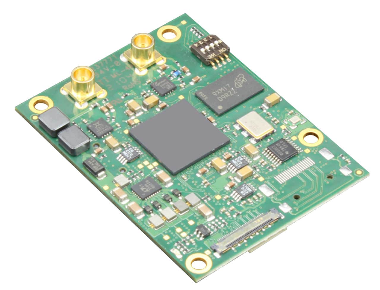
The TL4K1171 is a small form factor serial digital video (SDI) transmitter from AIVION. Camera video input signals are equalized, processed, and output over coaxial connectors. 6G-SDI output is compliant to SMPTE ST2081-10 MODE 1 mapping, Dual Link 3G-SDI output is compliant to SMPTE ST425-3, 2si mapping and 3G-SDI FHD output is compliant to SMPTE ST425-1 level A standards. Camera control is accomplished by a transparent full duplex communication channel. Physical interface between camera and camera controller / PC is based on RS232 or 3.3V TTL level. TLCK-B cable kit is available as accessory. Features: SDI Video Output Native signal processing for highest image quality MCX 75 Ohm straight coaxial connectors Resolution up to 3840x2160p @ 30fps 6G-SDI output of UHD formats Dual Link 3G-SDI output of UHD formats 3G-SDI output of FHD formats Automatic format detection Small Form Factor Small form factor 60mm x 46mm Camera Control RS232 level serial camera control interface 3.3V TTL level serial camera control interface Temperature Range and Power Ambient temperature (min/max): -5°C/+60°C Operating humidity range 20% to 80% Supply voltage 9V to 12V DC Compliance RoHS compliant (2002/05/EG and 2011/65/EU) UL/UR compliant Application 4K UHD and full HD integrated cameras based on Sony FCB-ER8550, FCB-ER8530, FCB-ER8300, FCB-ES8230 and FCB-EW9500H camera blocks Industrial, medical, security, law enforcement, video production Download TL4K1171 V1.0.1 Datasheet TL4K1171 Block Diagram Power Input: 9V to 12V DC (12.5V DC max.) regulated supply input voltage range Characteristics: PD = 7.0W typ. (FCB-ER8530 lens steady +TL4K1171) P TL4K1171 = 3.9W (typ.) (12V DC supply, 3840x2160@29.97fps, TA = 25°C, Humididty = 40%) Operating and Storage Conditions: Operating Conditions: Ambient temperature (min/max): -5°C/+60°C = 23°F/140°F - Humidity: 20%-80% TL4K1171 PCB Connectors J1 Power and Control IF (JST SM10B-SRSS-TB) Pin Signal 1 DC Supply voltage input 2 DC Supply voltage input 3 GND (0V) 4 GND (0V) 5 Reset- Pull pin 5 to GND(0V) for 1ms or longer for reset, leave open for normal operation. 6 GND (0V) 7 TXD_TTL (serial IF transmit 3.3V, optional) 8 RXD_TTL (serial IF receive 3.3V, optional) 9 RXD_232 (serial IF receive RS232 level) 10 TXD_232 (serial IF transmit RS232 level) J3 External Sync (JST SM08B-SRSS-TB) for use with FCB-ER8550 only Pin Signal 1 GND (0V) 2 External Sync Loop Out 3 GND (0V) 4 ACC_LED (Output signal from FCB-ER8550) 5 GND (0V) 6 External Sync Input 7 GND (0V) 8 SYNC_LOCK (Output signal from FCB-ER8550) J4 HDMI Input (KEL USL00-30L-A) 30wire microcoax connector for FCB-ER8xxx and FCB-EW9500H. Use 30wire micro coaxial cable supplied with cable kit. J6 Board feature extension connector Contact us for further notice J7 + J8 SDI output connector (Samtec MCX7-J-P-H-ST-TH1) Mode J7 J8 UHD 6GbpsUHD mode selection by switch#2 No output 6G-SDI UHD 3GbpsUHD mode selection by switch#2 Link1 of Dual Link 3G-SDI Link2 of Dual Link 3G-SDI FHDFHD operation requires camera to be set to 1080p60, 1080p59.94 or 1080p50 GND (0V) 3G-SDI (same signal as J7) Board Config Switch Switch# OFF ON 1 RS232 based camera control 3.3V TTL based camera control 2 6G-SDI UHD Output Mode DL 3G-SDI UHD Output Mode 3 Keep OFF Reserved 4 Keep OFF Reserved TL4K1171 PCB Outline TL4K1171 | Production Kit Partnumber Content TL4K1171 6 Gbps / Dual Link 3Gbps UHD-SDI Interface Board TLCK-B 1. TLCK-FL10-150 10 pin flying leads cable for power and control(RS232/TTL), length 15cm 2. TLCK-K30-200 30 pin KEL USL type micro coaxial cable, connector on both sides, length 20cm, Type 1:n TL4K1171-EXT | Evaluation Extension Partnumber Content EK-PA1100 Power supply and control interface board PS-TE10A12 12 V AC to DC external power supply with interchangeable blade kit for USA, Europe, United Kingdom and Australian. TL-EVK-USB2-A-MICROB USB 2.0 Cable with a USB 2.0-A male and a USB 2.0 micro-B male connector PTL-EVK-BRA Bracket and screws 2 x CK-MCX-BNC MCX to BNC connector cable
Product number: TL4K1171
Price on request
Sony FCB-ER8530
Key Features icons: resolution, optical zoom, digital zoom, image stabilization, HDMI video output, VISCA commandsSensor 1/2,5- type Exmor R CMOSResolution 8.51 MPVideo format 4K, 1080p, 720p, 480pOptical zoom (lens) 20 xDigital zoom 12 xSuper resolution zoom 30 xWidth 50Height 60Depth 93Video output HDMI 1.4bFOV 70.2 °Noise reduction Yes
Product number: FCB-ER8530
Price on request
Related HD Products
AIVION AZM-FS10L
Full-HD 10X optical zoom moduleFeaturesEffective numbers of Pixels: Approx. 2,100,000 pixelsImage sensor: 1/2.8 inch Sony Starvis CMOS Sensor (Progressive Scan)Lens: Optical 10x, f = 4.7 mm to 47.0 mm (F 1.6 to F 3.0)Horizontal viewing angle (wide to tele): 57.7 degrees(WIDE), 6.4 degrees(TELE)Digital Zoom: 12xVideo Output Digital: LVDS Digital ITU-R BT.1120 - YcbCr4:2:2 16bitsVideo Output Analog: SD CVBS (NTSC/PAL), 1.0Vp-p 75, CompositeCamera Control Interface: Visca Protocol
Product number: AZM-FS10L
Price on request
Sony FCB-EV7520
The FCB-EV7520 camera block incorporates a 1/2.8-type Exmor RTM CMOS sensor, providing Full-HD video with extraordinary sensitivity. In addition, the Sony block camera includes STARVISTM technology to realize high picture quality in visible light and near-infrared light. With 30x optical zoom and either HD or Full-HD capability, the camera inherits a multitude of Sony’s FCB features, including Auto ICR, Spherical Privacy Zone Masking, and Defog. Sony FCB-EV7520 Features 30x Enhanced Optical Zoom Digital Zoom 12x (360x with optical zoom) Full HD (1080p/60) Image Sensor 1/2.8-type Exmor R CMOS Minimum illumination Colour: 0.01 lx (F1.6,AGC on, 1/30 s) Defog · High Light Compensation · Wide Dynamic Range Super Image Stabilizer Auto IR-cut Filter Removal Spehrical privacy zone masking Noise reduction Slow AE response Datasheet Sony FCB-7520 Series Overview Features FCB-EV7520 Capture crisp, clear Full-HD (1080/60p) Even in low-light environments, the high-performance 1/2.8-type Exmor CMOS image sensor achieves outstanding Full-HD (1920 x 1080) picture quality. Progressive scanning assures smoother pictures with reduced blur – ideal for capturing the detail in moving images. Get a steadier picture with the image stabilizer. The camera's built-in image stabilizer function counters the effect of blurred, shaky images caused by low-frequency vibration. It is helpful for outdoor surveillance and traffic monitoring applications, mainly if the camera is used on a bridge or mounting pole where it is subjected to wind or mechanical vibration. Stable Zoom Image stabilizer and optical/digital zoom are combined to improve image quality while maintaining the original horizontal viewing angle. This does not affect the image size and reduces blu. 2D/3D noise reduction Advanced noise reduction technology filters noise from the image for clearer results, especially in low-light conditions. Noise reduction can be selected from five levels to suit a wide range of operating environments. Wide dynamic range Wide-D image processing technology allows one to see clear, detailed images in high-contrast or backlit environments. Models now support an extensive 130 dB dynamic range activated via the VISCA command. De-fog The de-fog feature allows more precise and natural viewing in foggy or misty scenes. The camera detects the haze level and automatically applies the required effects when this feature is activated. Depending on user requirements, the level of these effects can be adjusted via the VISCA command. HLC (High Light Compensation) HLC technology helps to improve, for example, the visibility of license plates when bright headlights are shot under low-light conditions. The bright parts in the image are masked and compensated automatically to achieve better visibility. Auto ICR (Auto IR-cut Filter Removal) In low-light conditions, the camera automatically switches from Day to Night mode, removing the IR-cut filter to boost sensitivity for clear pictures in near-darkness. The spherical privacy zone masking feature enables areas of view to be selectively masked for privacy. Masked areas are automatically interlocked with the camera’s pan/tilt/zoom movements. Privacy Zone Masking Privacy Zone Masking protects private objects and areas such as house windows, entrances, and exits within the camera’s range of vision but is not subject to surveillance. Privacy zones can be masked on the monitor to protect privacy. Wide range of features for versatile operation Versatile operation is ensured by a wide range of functions and adjustments, including White Balance modes; Picture effects (E-Flip, Nega Art, Black & White, Mirror Image, Colour Enhancement); Motion Detection/Alarm; Picture freeze; Temperature readout; Slow AE response; Electronic shutter/ slow shutter; and Title display/Camera mode display (English). Sony FCB-EV7520 Specifications Feature Sony FCB-EV7520 Image sensor 1/2.8-type Exmor R CMOS Image sensor (Number of effective pixels) Approx.2.13 Megapixels Signal system 1080p/59.94,1080p/50, 1080p/60, 1080p/30, 1080p/29.97, 1080p/25, 1080i/59.94, 1080i/50, 1080i/60, 1080i/30, 720p/59.94, 720p/50, 720p/60, 720p/30, 720p/29.97, 720p/25, NTSC, PAL Minimum illumination (50%) High sensitivity mode Colour: 0.01 lx (F1.6, AGC on, 1/30s) Minimum illumination (50%) Normal mode Colour: 0.1 lx (F1.6, AGC on, 1/30s) S/N ratio More than 50 dB Gain Auto/Manual Auto/Manual 0 dB to 50.0dB (0 to 28 steps +2 step/ total 15 steps) Gain Max. Gain Limit Max. Gain Limit 10.7 dB to 50.0 dB (6 to 28 steps +2 tep/ total 12 steps) Shutter speed 1/1 s to 1/10,000 s, 22 steps Sync system Internal Exposure control Auto, Manual, Priority mode (shutter priority & iris priority), Bright, EV compensation, Slow AE Backlight compensation Yes Aperture control 16 steps White balance Auto, ATW, Indoor, Outdoor, Outdoor Auto, Sodium Vapor Lamp (Fix/Auto/Outdoor Auto), One-push, Manual Lens 30x optical zoom f = 4.3 mm (wide) to 129.0 mm (tele) F1.6 to F4.7 Digital zoom 12x (360x with optical zoom) Focusing system Auto (Sensitivity: normal, low), One-push AF, Manual, Interval AF, Zoom Trigger AF, Focus compensation in ICR on Horizontal viewing angle 1080p mode 63.7° (wide end) to 2.3° (tele end) Horizontal viewing angle 720p mode 63.7° (wide end) to 2.3° (tele end) Horizontal viewing angle SD 47.8° (wide end) to 1.7° (tele end) Minimum object distance 10 mm (wide end) to 1200 mm (tele end) (Default: 300 mm) Auto ICR Yes Wide-D Yes (120 dB) Visibility Enhancer Yes De-fog Yes HLC Yes Noise reduction Yes (6 steps) Image stabilization Yes StableZoom Yes Spherical privacy zone masking Yes Motion detection Yes Alarm Yes Slow AE response Yes Picture effects E-Flip, Nega Art, Black & White, Mirror image, Colour enhancement Picture freeze Yes Slow shutter Yes Temperature readout Yes Title display Yes Camera mode display 20 characters/line, max. 11 lines Key switch control Yes Camera operation switch Yes Video output HD Analog N/A Video output HD Digital Digital:Y/Cb/Cr 4:2:2 via LVDS (Signal format conforms to SMPTE 274/SMPTE 296.) Video output SD VBS Camera control interface VISCA (CMOS 5 V level) Baud rate: 9.6 Kbps, 19.2 Kbps, 38.4 Kbps, 115.2 Kbps, Stop bit: 1 bit Power requirements 6.0 V to 12.0 V DC Power consumption - Focus inactive 3.2 W (zoom/focus inactive) Power consumption - Focus active 4.0 W (zoom/focus active) Operating temperature -5°C to +60°C (23°F to 140°F) Storage temperature -20°C to +60°C (-4°F to 140 °F) Operating humidity 20% to 80%, Absolute humidity: 36 g/m3 Storage humidity 20% to 95%, Absolute humidity: 36 g/m3 Dimensions (W x H x D) 50.0 x 60.0 x 89.7 mm (2 x 2 3/8 x 3 5/8 inches) Mass 255 g (9.0 oz) Sony FCB-7520 Dimensions Sony FCB-EV7520 Front Sony FCB-EV7520 Rear Sony FCB-EV7520 Top Sony FCB-EV7520 Bottom Sony FCB-EV7520 Left Sony FCB-EV7520 Right
Product number: FCB-EV7520
Price on request
TL7050 | Dual HD-SDI and HDMI Interface
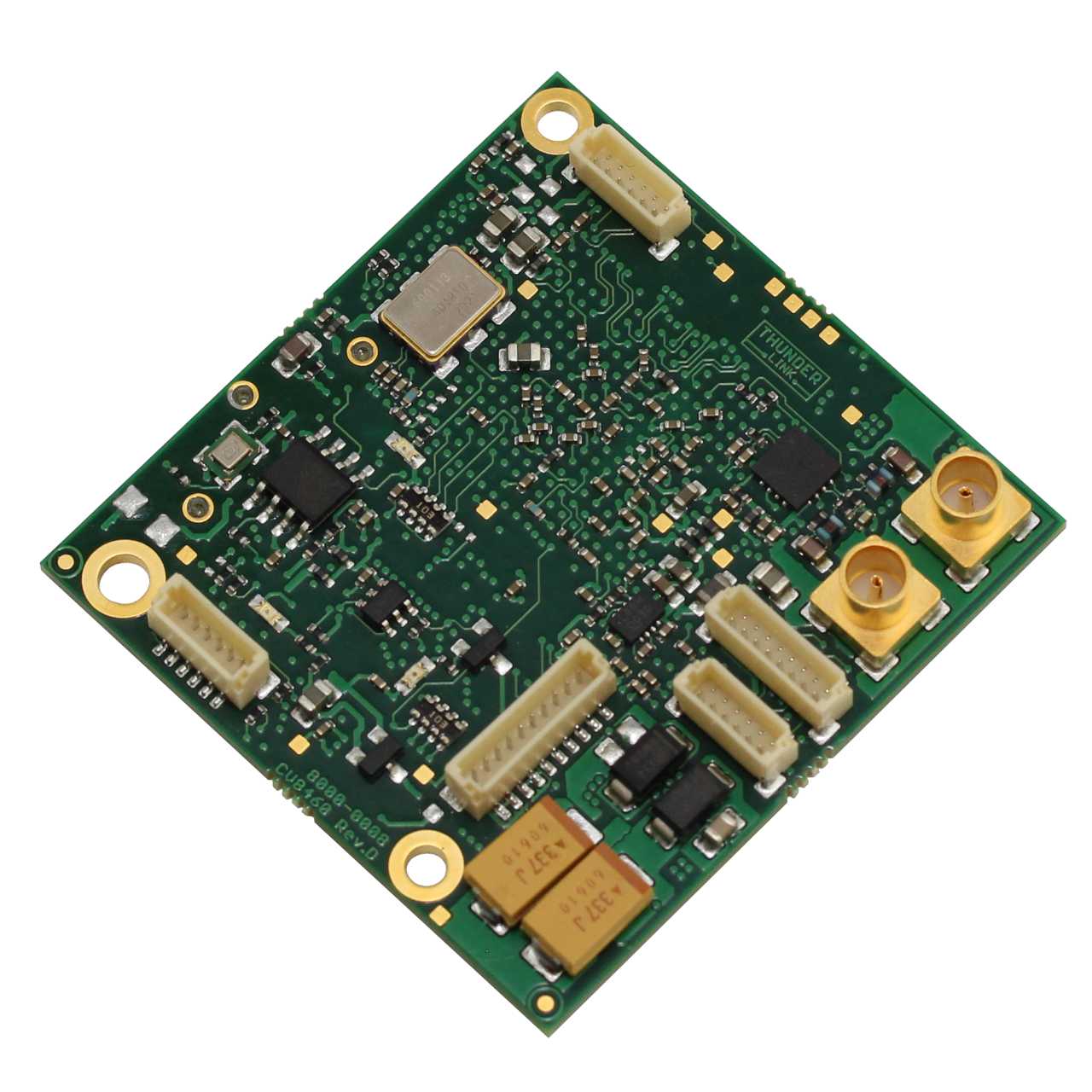
The TL7050 Dual 3G/HD-SDI and DVI(HDMI) Output Video Transceiver module from AIVION connect to the digital video interface (LVDS) of the block camera and support several progressive and interlace HDTV formats. As no analog to digital conversion is done on these modules, excellent output image quality is achieved. Features: Dual 3G-SDI/HD-SDI Output 3G-SDI output compliant to SMPTE 424M HD-SDI output compliant to SMPTE 292M 1080p60 /59.94 /50 /30 /29.97 /25 Hz 1080i60 /59.94 /50 Hz 720p60 /59.94 /50 /30 /29.97 /25Hz One HDMI Output HDMI connector (Kycon KDMIX_FS1V_WS) 1080p60 /59.94 /50 /30 /29.97 /25 Hz 1080i60 /59.94 /50 Hz 720p60 /59.94 /50 /30 /29.97 /25Hz Analog HDTV YPbPr and CVBS Output HDTV YPbPr video output signals Analog SDTV CVBS video output signals Camera Control RS232 and TTL level serial control interface Robust RS485 differential serial control interface Temperature Range and Power Temperature monitoring with alert function Operating ambient temperature range -5°C/+60°C = 23°F/140°F Operating humidity range 20% to 80% Supply voltage 12V DC regulated Video input and Compliance Full automatic video input standard detection Digital 4Ch./8Ch. LVDS video input from camera RoHS compliant (2002/05/EG and 2011/65/EU) UL/UR compliant Download TL7050 V 2.5.0 Datasheet TL7050 Block Diagram Power Input: 7V to 12V DC regulated (13V DC absolute maximum) for other camera blocks Characteristics: Power consumption TL7050: 260mA @ 12V DC (typ.) Operating and Storage Conditions: Ambient temperature (min/max) -5°C/+60°C = 23°F/140°F Humidity: 20% - 80% TL7050 PCB Connectors J8 HDMI connector Kycon KDMIX_FS1V_WS J3 Camera Interface KEL USL00-30L-A 30wire microcoax connector for camera IF. Use 30wire micro coaxial cable supplied with cable kit. J1 Power and Control JST SM10B-SRSS-TB Pin Signal 1 DC Supply voltage input 2 DC Supply voltage input 3 GND (0V) 4 GND (0V) 5 Reset / Shut Down, pull to GND to reset/shut down TL7050 and camera. For reset, pull to GND for one second or longer 6 GND (0V) 7 TXD_TTL (serial IF transmit, 3.3V) and/or temperature alert output 8 RXD_TTL (serial IF receive, 3.3V) 9 RXD_232 (serial IF receive, RS232 level) 10 TXD_232 (serial IF transmit, RS232 level) J2 RS485 Control IF JST SM08B-SRSS-TB Pin Signal 1 TXD_P (to controller) 2 TXD_N (to controller) 3 RXD_N (from controller) 4 RXD_P (from controller) 5 GND 6 3.45V typ. (max. current 50mA) J5 Analog component YPbPr and CVBS output Requires TL7050 extended cable kit Pin Signal 1 Pr 2 GND 3 Pb 4 GND 5 Y 6 GND 6 CVBS 6 GND J9, J10 75 ohms MCX coaxial jack 3G/HD-SDI output TL7050 PCB Outline Temperature Alert Function When board temperature exceeds 80°C (176°F), red LED will be switched on. In addition such an event can be signalled on connector J1/pin7 by setting switch 3 (temp alert enable) to ON position. - In case board temperature is equal to or over 80°C (176°F), level on J1/pin7 will be held constant low (< 0.4V) - In case board temperature is less than 80°C (176°F), level on J1/pin7 will be high (> 2.4V) Test Pattern Generator TL7050 has an integrated test pattern generator (TPG) which can be operated independent of any camera. The TPG can be enabled by setting onboard switch number 4 to ON position and repowering the TL7050 board. In addition one out of two test pattern and one out of four video standards can be selected by setting onboard switches 1, 2 and 3 accordingly. The following tables summarize all details. To enable TPG mode, please execute these steps: 1. Set video mode with switches 2 and 3 2. Set pattern with switch 1 3. Set switch 4 to ON to enable TPG mode 4. Switch TL7050 power off and on again Note: TPG operation can be enabled with or without any camera connected to TL7050 Analog Video Output TL7050 provides analog HDTV YPbPr and analog SDTV CVBS video output signals. These signals are directly taken from the camera. In some camera modes no or only limited analog video output might be available. Please refer to the related camera documentation. Reset Operation When applying power to TL7050, the camera is also automatically powered. During power up all functions on TL7050, are reset and initialized. During operation a manual reset can be applied by pulling pin no. 5 of connector J1 to 0V (GND). This resets also the camera. Camera Control Camera control can be done by connecting a PC or CCU via RS485, RS232 or serial 3.3V TTL interface to TL7050. The interface is passed through to the camera that all VISCA protocol based software can be used. Serial interface selection must be done be appropriate setting of switch-2. TL7050 | Production Kit Partnumber Content TL7050 HDMI-HD-SDI Board TLCK-B 1. TLCK-FL10-150 10 pin flying leads cable for power and control(RS232/TTL), length 15cm 2. TLCK-K30-200 30 pin KEL USL type micro coaxial cable, connector on both sides, length 20cm, Type 1:n TL7050-EXT | Evaluation Extension Partnumber Content EK-PA1100 Power supply and control interface board PS-TE10A12 12 V AC to DC external power supply with interchangeable blade kit for USA, Europe, United Kingdom and Australian. TL-EVK-USB2-A-MICROB USB 2.0 Cable with a USB 2.0-A male and a USB 2.0 micro-B male connector PTL-EVK-BRA Bracket and screws CK-MCX-BNC MCX to BNC connector cable TL-EVK-HDMI High Speed HDMI Cable. HDMI-A male > HDMI-A male 4K 2 meter
Product number: TL7050
Price on request
TL7051 | Dual HD-SDI Interface
The TL7051 Dual 3G/HD-SDI Output Video Transceiver module from AIVION connects to the digital video interface (LVDS) of the block camera and supports several progressive and interlace HDTV formats. As no analog to digital conversion is done on these modules, excellent output image quality is achieved. Features: Dual 3G-SDI/HD-SDI Output 3G-SDI output compliant to SMPTE 424M HD-SDI output compliant to SMPTE 292M 1080p60 /59.94 /50 /30 /29.97 /25 Hz 1080i60 /59.94 /50 Hz 720p60 /59.94 /50 /30 /29.97 /25Hz Video input Full automatic video input standard detection Digital 4Ch./8Ch. LVDS video input from camera Analog HDTV YPbPr and CVBS Output HDTV YPbPr video output signals Analog SDTV CVBS video output signals Camera Control RS232 and TTL level serial control interface Robust RS485 differential serial control interface Temperature Range and Power Temperature monitoring with alert function Operating ambient temperature range -5°C/+60°C = 23°F/140°F Operating humidity range 20% to 80% Supply voltage 12V DC regulated Compliance RoHS compliant (2002/05/EG and 2011/65/EU) UL/UR compliant Download TL7051 Revision D V.3.0.0 Datasheet TL7051 Block Diagram Power Input: 7V to 12V DC regulated (13V DC absolute maximum) for other camera blocks Operating Conditions: Ambient temperature (min/max) -5°C/+60°C = 23°F/140°F Humidity: 20% - 80% TL7051 PCB Connectors J9, J10 75 ohms MCX coaxial jack 3G/HD-SDI output J3 Camera Interface KEL USL00-30L-A 30wire microcoax connector for camera IF. Use 30wire micro coaxial cable supplied with cable kit. J1 Power and Control JST SM10B-SRSS-TB Pin Signal 1 DC Supply voltage input 2 DC Supply voltage input 3 GND (0V) 4 GND (0V) 5 Reset / Shut Down, pull to GND to reset/shut down TL7051 and camera. For reset, pull to GND for one second or longer 6 GND (0V) 7 TXD_TTL (serial IF transmit, 3.3V) and/or temperature alert output 8 RXD_TTL (serial IF receive, 3.3V) 9 RXD_232 (serial IF receive, RS232 level) 10 TXD_232 (serial IF transmit, RS232 level) J2 RS485 Control IF JST SM08B-SRSS-TB Pin Signal 1 TXD_P (to controller) 2 TXD_N (to controller) 3 RXD_N (from controller) 4 RXD_P (from controller) 5 GND 6 3.45V typ. (max. current 50mA) J5 Analog component YPbPr and CVBS output Requires TL7051 extended cable kit Pin Signal 1 Pr 2 GND 3 Pb 4 GND 5 Y 6 GND 6 CVBS 6 GND TL7051 PCB Outline Temperature Alert Function When board temperature exceeds 80°C (176°F), red LED will be switched on. In addition such an event can be signalled on connector J1/pin7 by setting switch 3 (temp alert enable) to ON position. - In case board temperature is equal to or over 80°C (176°F), level on J1/pin7 will be held constant low ( < 0.4V) - In case board temperature is less than 80°C (176°F), level on J1/pin7 will be high (> 2.4V) Test Pattern Generator TL7051 has an integrated test pattern generator (TPG) which can be operated independent of any camera. The TPG can be enabled by setting onboard switch number 4 to ON position and repowering the TL7051 board. In addition one out of two test pattern and one out of four video standards can be selected by setting onboard switches 1, 2 and 3 accordingly. The following tables summarize all details. To enable TPG mode, please execute these steps: 1. Set video mode with switches 2 and 3 2. Set pattern with switch 1 3. Set switch 4 to ON to enable TPG mode 4. Switch TL7051 power off and on again Note: TPG operation can be enabled with or without any camera connected to TL7051 Analog Video Output TL7051 provides analog HDTV YPbPr and analog SDTV CVBS video output signals. These signals are directly taken from the camera. In some camera modes no or only limited analog video output might be available. Please refer to the related camera documentation. Reset Operation When applying power to TL7051, the camera is also automatically powered. During power up all functions on TL7051, are reset and initialized. During operation a manual reset can be applied by pulling pin no. 5 of connector J1 to 0V (GND). This resets also the camera. Camera Control Camera control can be done by connecting a PC or CCU via RS485, RS232 or serial 3.3V TTL interface to TL7051. The interface is passed through to the camera that all VISCA protocol based software can be used. Serial interface selection must be done be appropriate setting of switch-2. TL7051 | Production Kit Partnumber Content TL7051 3G-SDI/HD-SDI Board TLCK-B 1. TLCK-FL10-150 10 pin flying leads cable for power and control(RS232/TTL), length 15cm 2. TLCK-K30-200 30 pin KEL USL type micro coaxial cable, connector on both sides, length 20cm, Type 1:n TL7051-EXT | Evaluation Extension Partnumber Content EK-PA1100 Power supply and control interface board PS-TE10A12 12 V AC to DC external power supply with interchangeable blade kit for USA, Europe, United Kingdom and Australian. TL-EVK-USB2-A-MICROB USB 2.0 Cable with a USB 2.0-A male and a USB 2.0 micro-B male connector PTL-EVK-BRA Bracket and screws CK-MCX-BNC MCX to BNC connector cable
Product number: TL7051
Price on request
TL7052 | HDMI Interface
The TL7052 DVI(HDMI) Output Video Transceiver module from AIVION connects to the digital video interface (LVDS) of the block camera and support several progressive and interlace HDTV formats. As no analog to digital conversion is done on these modules, excellent output image quality is achieved. Features: Video input Full automatic video input standard detection Digital 4Ch./8Ch. LVDS video input from camera One HDMI Output HDMI connector (Kycon KDMIX_FS1V_WS) 1080p60 /59.94 /50 /30 /29.97 /25 Hz 1080i60 /59.94 /50 Hz 720p60 /59.94 /50 /30 /29.97 /25Hz Analog HDTV YPbPr and CVBS Output HDTV YPbPr video output signals Analog SDTV CVBS video output signals Camera Control RS232 and TTL level serial control interface Temperature Range and Power Temperature monitoring with alert function Operating ambient temperature range -5°C/+60°C = 23°F/140°F Operating humidity range 20% to 80% Supply voltage 12V DC regulated Compliance RoHS compliant (2002/05/EG and 2011/65/EU) UL/UR compliant Download TL7052 V 2.4.0 Datasheet TL7052 Block Diagram Power Input: 7V to 12V DC regulated (13V DC absolute maximum) for other camera blocks Operating Conditions: Ambient temperature (min/max) -5°C/+60°C = 23°F/140°F Humidity: 20% - 80% TL7052 PCB Connectors J8 HDMI connector Kycon KDMIX_FS1V_WS J3 Camera Interface KEL USL00-30L-A 30wire microcoax connector for camera IF. Use 30wire micro coaxial cable supplied with cable kit. J1 Power and Control JST SM10B-SRSS-TB Pin Signal 1 DC Supply voltage input 2 DC Supply voltage input 3 GND (0V) 4 GND (0V) 5 Reset / Shut Down, pull to GND to reset/shut down TL7052 and camera. For reset, pull to GND for one second or longer 6 GND (0V) 7 TXD_TTL (serial IF transmit, 3.3V) and/or temperature alert output 8 RXD_TTL (serial IF receive, 3.3V) 9 RXD_232 (serial IF receive, RS232 level) 10 TXD_232 (serial IF transmit, RS232 level) J5 Analog component YPbPr and CVBS output Requires TL7052 extended cable kit Pin Signal 1 Pr 2 GND 3 Pb 4 GND 5 Y 6 GND 6 CVBS 6 GND J4 24pin FFC Connector Power, Reset, Serial Control IF, analog Video TL7052 PCB Outline Temperature Alert Function When board temperature exceeds 80°C (176°F), red LED will be switched on. In addition such an event can be signalled on connector J1/pin7 by setting switch 3 (temp alert enable) to ON position. - In case board temperature is equal to or over 80°C (176°F), level on J1/pin7 will be held constant low (< 0.4V) - In case board temperature is less than 80°C (176°F), level on J1/pin7 will be high (> 2.4V) Test Pattern Generator TL7052 has an integrated test pattern generator (TPG) which can be operated independent of any camera. The TPG can be enabled by setting onboard switch number 4 to ON position and repowering the TL7052 board. In addition one out of two test pattern and one out of four video standards can be selected by setting onboard switches 1, 2 and 3 accordingly. The following tables summarize all details. To enable TPG mode, please execute these steps: 1. Set video mode with switches 2 and 3 2. Set pattern with switch 1 3. Set switch 4 to ON to enable TPG mode 4. Switch TL7052 power off and on again Note: TPG operation can be enabled with or without any camera connected to TL7052 Analog Video Output TL7052 provides analog HDTV YPbPr and analog SDTV CVBS video output signals. These signals are directly taken from the camera. In some camera modes no or only limited analog video output might be available. Please refer to the related camera documentation. Reset Operation When applying power to TL7052, the camera is also automatically powered. During power up all functions on TL7052, are reset and initialized. During operation a manual reset can be applied by pulling pin no. 5 of connector J1 to 0V (GND). This resets also the camera. Camera Control Camera control can be done by connecting a PC or CCU via RS485, RS232 or serial 3.3V TTL interface to TL7052. The interface is passed through to the camera that all VISCA protocol based software can be used. Serial interface selection must be done be appropriate setting of switch-2. TL7052 | Production Kit Partnumber Content TL7052 HDMI Board TLCK-B 1. TLCK-FL10-150 10 pin flying leads cable for power and control(RS232/TTL), length 15cm 2. TLCK-K30-200 30 pin KEL USL type micro coaxial cable, connector on both sides, length 20cm, Type 1:n TL7052-EXT | Evaluation Extension Partnumber Content EK-PA1100 Power supply and control interface board PS-TE10A12 12 V AC to DC external power supply with interchangeable blade kit for USA, Europe, United Kingdom and Australian. TL-EVK-USB2-A-MICROB USB 2.0 Cable with a USB 2.0-A male and a USB 2.0 micro-B male connector PTL-EVK-BRA Bracket and screws TL-EVK-HDMI High Speed HDMI Cable. HDMI-A male > HDMI-A male 4K 2 meter
Product number: TL7052
Price on request
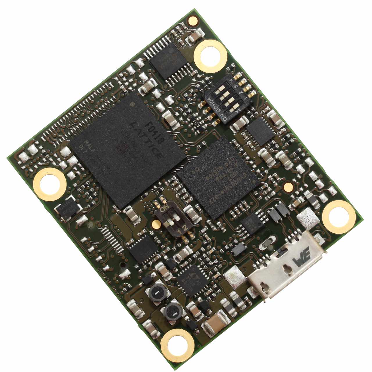
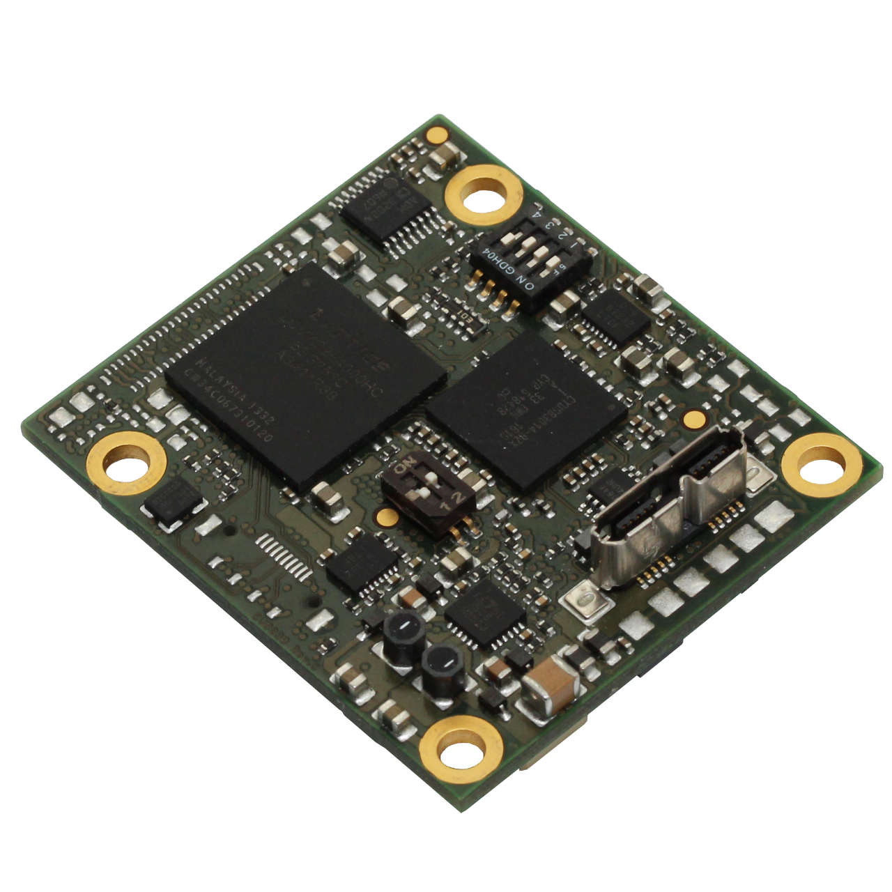
TL6032 | USB 3.0 Horizontal Micro B Interface
The TL6032 interface is a HDTV USB 3.0 compliant video streaming capture solution from AIVION. As no analog to digital conversion is done on these modules, excellent output image quality is guaranteed. Features: USB 3.0 Video Output Up to 1080p30 uncompressed HDTV video data, 4:2:2 YUV format 1920x1080p @ 25Hz, 29.97Hz, 30 Hz 1280x720p @ 50Hz, 59.94Hz, 60Hz, 25Hz, 29.97Hz, 30Hz The module receives digital video signals at the input and sends UVC (USB Video Class) compliant data packets containing digital video payload to a connected host computer Small Form Factor Small form factor 45mm x 40mm USB Operates always as Super Speed USB3.0 device (Host or OTG operation modes are not supported) Host computer must run a UVC capable operating system Parallel up- and downstream of camera control and status data is possible (USB CDC) Power Full USB bus powered camera solution possible depending on camera Power supply voltage for camera is generated onboard Allows an external power supply Compliance RoHS compliant (2002/05/EG and 2011/65/EU) UL/UR compliant Temperature Range Ambient temperature (min/max): -5°C/+60°C = 23°F/140°F Operating humidity range 20% to 80% Download TL6032 V2.0.0 Datasheet TL6032 Block Diagram Power Input: 5V DC from USB3 port Characteristics: Power consumption (FCB-EV75xx + TL6035) 5.6W Power consumption (FCB-SE600 + TL6035) 3.5W (cam motors inactive) Power consumption TL6035: 2.7W/540mA@5V DC (max.) Operating and Storage Conditions: Operating Conditions: Ambient temperature (min/max): -5°C/+60°C = 23°F/140°F - Humidity: 20%-80% Storage Conditions: Temperature (min/max): -20°C/+60°C = -4°F/ 140°F - Humidity: 20%-80% TL6032 PCB Connectors J6 USB3 microB connector Horizontal J2 LVDS Video In 30wire microcoax connector for 4K Block Cameras. Use 30wire micro coaxial cable supplied with cable kit. J7 External Power Supply Pin Signal 1 Input voltage 5V to 7V DC 2 Input voltage 5V to 7V DC 3 System reset, pull to GND for reset 4 GND (0V) 5 GND (0V) J9 RS232 UART Connector Pin Signal 1 to 7 do not connect 8 GND 9 RXD (host to camera) 10 TXD (camera to host) TL6032 PCB Outline Camera Power Camera supply voltage is generated on TL6032 by a boost converter circuit. This circuit provides 9.55V DC (+/-3%) to the camera. NOTE: USB3.0 is specified for 4.5W maximum output power per USB3.0 port on a computer. However, many main boards used in desktop computer systems are able to provide more USB3 output power. In case of notebook and laptop computers, IPCs and SBCs, it has to be checked case by case if USB3 output power is sufficient or not. This is in the sole responsibility of the user of TL6032. TL6032 EXTERNAL POWER OPTION: TL6032 allows to use an external power supply in case USB3 power of the used computer is not sufficient. As described on page 3 of this document, external power can be input on J7. Using a voltage of 6V DC is recommended. In case an external power supply is used, this voltage is used on TL6032 for the camera supply boost converter only. All other electronic devices on TL6032 are always powered from USB3 port. No adjustments on TL6032 are required for using external power. When powering up such a configuration, external power must be supplied before or coincident with USB3 power. Host (PC) - Device Communication TL6032 operates always as USB device which sends UVC compliant video data to a host PC. The host also communicates with the TL6032 via a serial communication channel (USB UART). Connecting the TL6032 to the Host PC Operating System Support TL6032 can be used with operating systems which fully support USB UVC type data and communication. Currently supported Microsoft Windows operating systems: Windows 7 (32 and 64bit) Windows 8.1 (32 and 64bit) Windows 10 (64bit, version 1511) Driver Requirements Full UVC compliant driver is required. Such drivers are supplied with Microsoft Windows 7 and 8 . Manual driver installation is not necessary. For the USB UART feature, the class driver is used. Aivion provides suitable driver assignment files. Win 10 does not require such a driver assignment file. Video Application on Host PC Video display and recording can be done with standard application programs like VLC player, Mplayer or similar. VLC and Mplayer are open source based applications and can be free downloaded. If users want to design their own applications software, they are free to do so. All software programming tasks are OS based and have to be built upon UVC drivers. For further information please refer to Microsoft Windows API information. Controlling TL6032 from the Host PC via USB UART TL6032 supports the USB UART functionality. FCB cameras connected to TL6032 can be controlled via a virtual COM port. Any host software which uses COM ports can be used. The USB UART channel is transparent for any protocol. Communication speed is 9600bit/ s or 38400bit/s maximum. Other COM port settings are (8N1). TL6032 | Production Kit Partnumber Content TL6032 USB 3.0 Board TLCK-K30-200 30 pin KEL USL type micro coaxial cable, connector on both sides, length 20cm, Type 1:n TL6032-EXT | Evaluation Extension Partnumber Content EK-PA1100-USB Power supply and control interface board PS-TE10A05 5 V AC to DC external power supply with interchangeable blade kit for USA, Europe, United Kingdom and Australian. TL-EVK-USB-SA USB to serial adapter TL-EVK-BRA Bracket and screws TL-EVK-USB3-A-MICROB USB 3.0 Cable with a USB 3.0-A male and a USB 3.0 micro-B male connector
Product number: TL6032
Price on request
TL6035 | USB 3.0, Vertical Micro B Connector
The TL6035 USB 3.0 interface board from AIVION is a tiny and easy to use HDTV USB3.0 video capture interface for the block cameras. The module receives digital video signals and sends UVC (USB Videl Class) compliant data packets to a connected host computer. Our compact TL6035 module enables the design of small camera systems that need only a single connection between camera and PC. Video stream, control data and power will be connected by a USB 3.0 cable. For camera blocks that need more than 900 mA during startup a Y-cable is required. Features: USB 3.0 Video Output Up to 1080p30 uncompressed HDTV video data, 4:2:2 YUV format 1920x1080p @ 25Hz, 29.97Hz, 30 Hz 1280x720p @ 50Hz, 59.94Hz, 60Hz, 25Hz, 29.97Hz, 30Hz The module receives digital video signals at the input and sends UVC (USB Video Class) compliant data packets containing digital video payload to a connected host computer Small Form Factor Small form factor 45mm x 40mm USB Operates always as Super Speed USB3.0 device (Host or OTG operation modes are not supported) Host computer must run a UVC capable operating system Parallel up- and downstream of camera control and status data is possible (USB CDC) Power Full USB bus powered camera solution possible depending on camera Power supply voltage for camera is generated onboard Allows an external power supply Compliance RoHS compliant (2002/05/EG and 2011/65/EU) UL/UR compliant Temperature Range Ambient temperature (min/max): -5°C/+60°C = 23°F/140°F Operating humidity range 20% to 80% Datasheet TL6035 V2.0.0 Application Note TL6035 TL6035 Block Diagram Power Input: 5V DC from USB3 port Characteristics: Power consumption (FCB-EV75xx + TL6035) 5.6W Power consumption (FCB-SE600 + TL6035) 3.5W (cam motors inactive) Power consumption TL6035: 2.7W/540mA@5V DC (max.) Operating and Storage Conditions: Operating Conditions: Ambient temperature (min/max): -5°C/+60°C = 23°F/140°F - Humidity: 20%-80% Storage Conditions: Temperature (min/max): -20°C/+60°C = -4°F/ 140°F - Humidity: 20%-80% TL6035 PCB Connectors J6 USB3 microB connector Vertical J2 LVDS Video In 30wire microcoax connector for 4K Block Cameras. Use 30wire micro coaxial cable supplied with cable kit. J7 External Power Supply Pin Signal 1 Input voltage 5V to 7V DC 2 Input voltage 5V to 7V DC 3 System reset, pull to GND for reset 4 GND (0V) 5 GND (0V) J9 RS232 UART Connector Pin Signal 1 to 7 do not connect 8 GND 9 RXD (host to camera) 10 TXD (camera to host) TL6035 PCB Outline Camera Power Camera supply voltage is generated on TL6035 by a boost converter circuit. This circuit provides 9.55V DC (+/-3%) to the camera. NOTE: USB3.0 is specified for 4.5W maximum output power per USB3.0 port on a computer. However, many main boards used in desktop computer systems are able to provide more USB3 output power. In case of notebook and laptop computers, IPCs and SBCs, it has to be checked case by case if USB3 output power is sufficient or not. This is in the sole responsibility of the user of TL6035. TL6035 EXTERNAL POWER OPTION: TL6035 allows to use an external power supply in case USB3 power of the used computer is not sufficient. As described on page 3 of this document, external power can be input on J7. Using a voltage of 6V DC is recommended. In case an external power supply is used, this voltage is used on TL6035 for the camera supply boost converter only. All other electronic devices on TL6035 are always powered from USB3 port. No adjustments on TL6035 are required for using external power. When powering up such a configuration, external power must be supplied before or coincident with USB3 power. Host (PC) - Device Communication TL6035 operates always as USB device which sends UVC compliant video data to a host PC. The host also communicates with the TL6035 via a serial communication channel (USB UART). Connecting the TL6035 to the Host PC Operating System Support TL6035 can be used with operating systems which fully support USB UVC type data and communication. Currently supported Microsoft Windows operating systems: Windows 7 (32 and 64bit) Windows 8.1 (32 and 64bit) Windows 10 (64bit, version 1511) Driver Requirements Full UVC compliant driver is required. Such drivers are supplied with Microsoft Windows 7 and 8 . Manual driver installation is not necessary. For the USB UART feature, the class driver is used. Aivion provides suitable driver assignment files. Win 10 does not require such a driver assignment file. Video Application on Host PC Video display and recording can be done with standard application programs like VLC player, Mplayer or similar. VLC and Mplayer are open source based applications and can be free downloaded. If users want to design their own applications software, they are free to do so. All software programming tasks are OS based and have to be built upon UVC drivers. For further information please refer to Microsoft Windows API information. Controlling TL6035 from the Host PC via USB UART TL6035 supports the USB UART functionality. FCB cameras connected to TL6035 can be controlled via a virtual COM port. Any host software which uses COM ports can be used. The USB UART channel is transparent for any protocol. Communication speed is 9600bit/ s or 38400bit/s maximum. Other COM port settings are (8N1). TL6035 | Production Kit Partnumber Content TL6035 USB 3.0 Vertical Micro B USB Board TLCK-K30-200 30 pin KEL USL type micro coaxial cable, connector on both sides, length 20cm, Type 1:n TL6035-EXT | Evaluation Extension Partnumber Content EK-PA1100-USB Power supply and control interface board PS-TE10A05 5 V AC to DC external power supply with interchangeable blade kit for USA, Europe, United Kingdom and Australian. TL-EVK-USB-SA USB to serial adapter TL-EVK-BRA Bracket and screws TL-EVK-USB3-A-MICROB USB 3.0 Cable with a USB 3.0-A male and a USB 3.0 micro-B male connector
Product number: TL6035
Price on request
